Yes…it’s TRUE. I used a 3D printer to solve a problem I have had with my Celestron CGEM mount ever since I bought it. Because I am a retired Electrical Engineer I have always been focused on finding ways to improve my guiding. The first issue I focused on was Periodic Error Correction (PEC). My very old CGEM is of the vintage when Celestron used non-integer gearing in their mounts. This resulting in a periodic error that took multiple rotations of the worm gear to repeat. Specifically the periodic error requires 3 rotations of the worm gear for the error to repeat. The PEC logic they installed in the CGEM assumed that the periodic error repeated for every rotation of the worm gear. My take on this issue is that most CGEM users didn’t bother trying to train their mount PEC. The PEC logic did work but crudely. Most CGEM users ended up using short exposures to guide their mount without using the Celestron PEC logic.
Background Info
It took me several years of experimenting but I finally figured out how to create a program that would talk to my CGEM using many of the NexStar communication Protocol commands. This gave me access to the RAW RA and DEC encoder values and to all of the PEC commands for finding the RA Index which synchronizes the RAW RA encoder values to the position of the worm gear. My program can tell the mount to seek the RA Index while monitoring the RAW RA encoder values. It then uses this information to build and replay a PEC that is 3 worm gear rotations in length. The PEC values are sampled every second and one rotation of the worm gear takes 480 seconds. The PEC table contains 1,440 values…one for each second. I have been using this program for years now and I can typically autoguide my CGEM with a total RMS guiding error of 0.5″ which I think is great. In order to continue using the NexStar commands I have to continue using the NexRemote application. I am probably the only guy still using NexRemote on their Windows 11 computer. It works fine…but their are tricks to getting it to work.
What about those 3D printed gears???
One bug in my PEC program is that it didn’t know which of the 3 wormgear rotations were active at any given time. I ended up using a variance calculation that could eventually tell which of the 3 wormgear rotations was best at any given time. This can only be done while autoguiding is active so it is tricky to implement. This variance calculation took several minutes to reach a conclusion and sometimes it would guess wrong. Somehow I needed to invent a hardware solution that would tell me which of the three worm gear rotations was active every time I used my mount. I don’t have an observatory so everything is assembled and taken down every night. This meant that it had to have a memory that didn’t require power. I had thought about using gears for a few years but I didn’t bother trying to fabricate anything. A family member told me that they had bought a 3D printer and offered to let me use it for a month or two. Being able to create 3D printed gears got me thinking.
I went thru three different iterations of 3D printed gears before I found something that would fit into the RA motor/gearbox
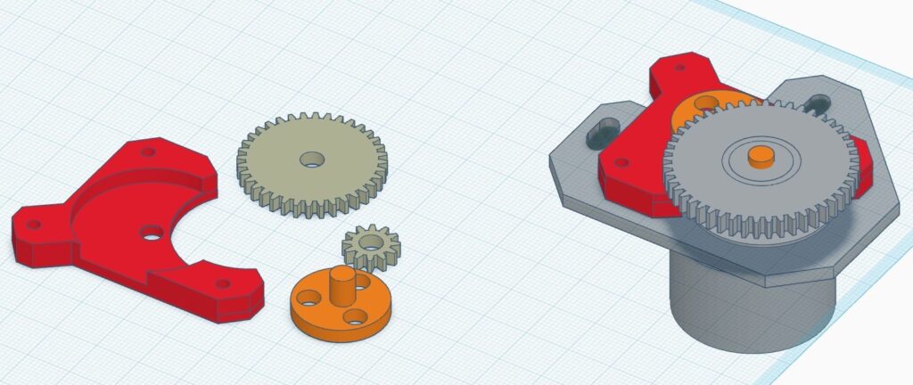
On the left side are the 3D printed parts as shown in a great 3D design program called TinkerCAD. Those two gears are only 3mm thick. The small gear has 12 teeth and the large gear has 36 teeth so they have a 3:1 ratio between them. On the right side is the fully assembled project. The grey objects are the RA motor, gearbox, mounting plate and spur gear. The spur gear is connected to another spur gear which directly turns the worm gear. Both spur gears are identical.
To attached the 3D printed parts I have to loosen two grub screws which secure the spur gear to the motor/gearbox shaft. The spur gear is then lifted off the shaft and the 12 tooth 3D printed gear is tightly pressed onto the shaft so that it close, but not touching, the mount plate. The fit of the 12 tooth gear and the shaft is very tight so that this gear does not slip. The spur gear is then repositioned onto the shaft and secured with its two grub screws. When the spur gear turns one revolution the 12 tooth gear will also turn one revolution and the worm gear will also turn one revolution.
The large 3D printed gear is placed into the circular cut-out of the red colored holder. The orange colored object with the three holes is then inserted into the bottom of the holder so that the orange shaft can be inserted into the large gear. The orange shaft is loosely fitted into the holder and tightly fitted to the large gear.
The assembled 3D project is now flipped over and then placed onto to grey mounting plate so that the large and small 3D printed gear teeth are interlocked with a small spacing. The holder is then fixed in position using two screws. These holes had to be drilled into the mount plate. Now when the spur gear turns. The two 3D printed gears also turn. The orange part with the three holes turns with the large gear. Because of the 3:1 gear ratio between the large and small gears the large gear turns one revolution for every 3 rotations of the spur gear.
Why are there holes in the orange part?
Those 5mm diameter holes in the orange part are where two 5mm dia magnets are to be installed. One magnet is installed so that it’s north pole is up. The other magnet is installed so that it’s south pole is up. These are friction fits. The spur gear is made from brass which is weakly magnetic so I don’t expect the magnets to get loose.
The final detail is a sensor called an A1302 hall effect device. This is an analog device that can sense magnetic fields and can tell the difference between a magnets north or south pole. The sensor is mount so that the magnets pass underneath it. The three holes are equally spaced. With a little bit of fiddling I was able to position the “orange part” so that when rotation #1 is active the north pole is underneath the sensor. On rotation #2 the south pole is underneath the sensor. On rotation #3 neither magnet is underneath the sensor.

The picture on the left is looking down on the 48 tooth spur gear. You can see the two 5mm magnets mounted on the “orange part” mentioned earlier. The tiny black sensor with it’s three wires is held in position using hot melt glue. On the back side of the “orange part” is a shaft that passes thru the holder and connects to the large 36 tooth gear. If you look closely just slightly upwards and to the right of the “orange part” you can see a few of the teeth of the large gear visible underneath the holder.
The picture on the right is a side view that shows all the stuff that exists under the spur gear. At the bottom right of this image is the pre-existing Celestron proximity switch which is used to find the PEC index. The thin black disk that rotates thru this proximity switch has a narrow radial slot cut in it which this proximity switch detects. This black disk is mounted to the spur gear so it is removed with the spur gear. The Celestron proximity switch also needs to be removed when removing the spur gear. Underneath this thin black disk is the small 12 tooth gear. I estimate there is only 4mm of space here which is just enough to mount the 3mm thick 3D printed small gear. A portion of the large 36 tooth 3D printed gear is visible.
There is virtually no space available in this location. Celestron had to carve a circular void into the mount’s metal housing interior just to accommodate the spur gear. That’s why all of the 3D printed stuff is underneath the spur gear. I also painted the inside of the metal housing to to ensure that the metal housing would not touch the A1302 wires.

This is a graph of how the A1302 sensor and the 3D printed gears work together. The red pen is the PEC Index for my CGEM. The index value ranges from 0 to 1439. Each revolution of the worm gear is equal to 480 so 1439 represents the 3 rotations of the worm gear. The blue pen is the signal from the A1302 Hall effect device. I have it wired to an Arduino Nano and my astronomy system reads the values into my computer. The Y values have been scaled such that the units for the A1302 are Gauss. Negative values are North and positive values are South. When the gauss value is <-200 I know it is cycle #1. If the gauss value is >200 I know it is cycle #2. I know it is cycle #3 if the index value is between 1000 and 1300 the gauss absolute value is < 200.
The sensor is power by the 5V supply and it’s analog input is connected to analog input 6. The code in the Nano is
A1302 = ((analogRead(6)-509)*3.756 + 19*A1302)/20; //Units are Gauss +ve=South Pole -ve=North Pole
The A1302 variable is declared at the top of the program as being a static float. The zero gauss offset is 509 counts and the conversion to gauss is 3.756. I also included a 20 sample first order averaging to reduce electrical and sensor noise. The A1302 value is sent via USB to my computer every 500mS.
I have used it for 10 nights now and it works fine.
Peter